A funny sightseeing, where public can contribute (and sometimes reduce). Idea author has tied the first tie there in 2015 and since then the exposition has grown.
Bridge with neckties in Lithuania
Leave a reply
A funny sightseeing, where public can contribute (and sometimes reduce). Idea author has tied the first tie there in 2015 and since then the exposition has grown.
Exposition was presented with the items from the collection of Alexandre Vassiljev.
Very expressive, showing the moods of that epochs and the evolutional way of the costumes.

With a bit of efforts I was able to free up some disc space. VIDA installation needed that. Now I know, how my car is assembled and working.
Yesterday, I have dismantled part of interior to hide a wire for the dash cam. The wire, that came with the cam is too long, about 3 meters, and disturbs driving, not saying, that it also takes valuable socket on the dash board.
During the process it came out, that I haven’t such a long mini-USB cables. Didn’t start to cut original one in case of. So I just visited nearby mall with partly disassembled interior and that was just half an hour before mall was closed. Fortunately got there ideally suit cable.
Installation took no more than 10 minutes. There is a large free space between roof and the holster. The most challenging was hiding the wire between the front pillar and glove compartment. There was everything isolated and the USB plug was clinging to it.
I did took power from the USB accessory unit wire, that was also available at the glove compartment.
Interior disassembling and the next assembly took much more time, than the installation. VIDA is not very picky on details, so there were some unexpected latches. And when you have unscrewed all the required screws and the gentle pulling does not help to remove the detail, you have to check surroundings thoroughly to not to break anything. Eventually it came out, that you have just to pull harder. Latches are good there.
The next step would be a power steering oil cooler installation. I would have to dismantle front bumper for that and may be the cooling fan from the block of coolers.
For a long time I had an old photo flash FIL 11M manufactured in USSR by local factory Norma.
There was a high-voltage synchrocontact on the flash, which suited ideally with a film cameras Zenit.
Now, film camera times have passed and they were exchanged by digital cameras. However photography principles are left the same and there is a still need in the light, including flash light. After playing enough with my Canon EX420 flash, I have decided to add a second flash into my lightning schemes. Buying original flashes is an expensive joy, buying chinese – is a lottery. So I thought I could use an existing old flash somehow.
After googling for a while, I have found out, that contemporary cameras have low-voltage contacts, and therefore some adapter is needed. However, wires is not the convenient way of connecting camera and the flash, and there are other means of synchronizing them using light, when the second flash is triggered by the light received from the first flash. As soon as the light reaches the synchronizer almost immediately, but working time and exposure time are long, comparing to this, we can say, that both flashes will trigger concurrently.
Further search got me to an excellent website osipoff.ru, where different photo flash related electronics is being discussed and where are the lots of synchronizer schematics.
I quickly found the simple schematic “Mercedes”, by Veryutin with lots of positive feedback. This schematic can withstand high voltages up to 300 V, which is according to FIL 11M specs. I tryed to made the schematic from the components I had and trying to make it as small as possible. So SMD parts were the primary choice. I had only 0805 sized resistors and they can hold only up to 150 volts, so I had to make a large 22 ohms resistance of several serially connected resistors.
Synchronizer started to work from the first time. Unfortunately it immediately came out, that this schematic is not suitable for synchronizing with contemporary consumer cameras, because they do flash two times. The first one is so-called pre-flash to check the exposure value and set the right values for the main flash and for the aperture. The second one is the main flash with correct parameters. With “Mercedes” synchronizer, the second flash was triggered during pre-flash and so the photo was underexposured as a result.
After some research, I have found couple of second-flash capable synchronizers. This time I did not take Veryutins’ schematics, because it has odd values on it and there were no few of the required parts left. But I have found another schematic, which was essentially the same and started to assemble it. It took twice the time to get the device assembled, but it did not worked right after that. I have checked it with the multimeter and found an unsoldered contact. After soldering it together, the schematic started to work properly.
Tried it in both modes. It synchronized perfectly after first and after second flashes.
Now it is time to make a photo set with the new lightning schemes.
FTDI, large semiconductor manufacturer, recently released an update for its popular device drivers, that was bringing counterfeit chips into not usable state. However this made users uproar, because no end-user has an option to find out whether he obtains device with legal or counterfeit ICs. Luckily, FTDI has removed that update at the moment and there are ways to bring the devices back to life, but they still threat users with other options to annoy counterfeit users. The full story you can read, for example here: FTDI on counterfeit chip bricking: “Our intentions were honorable”
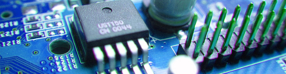
But let’s look closer at the chip, all the talks are about.
FT232RL is an extremely convenient chip. It serves as a bridge between USB virtual serial port on PC and UART on the device. Besides that it supports bit-bang mode, which makes it to support multiple protocols (e.g. SPI, I2C, etc.) in a software way. And as a bonus it has an internal circuitry to interface either 5V or 3V3 devices.
From a programming point of view, you have just to plug the device into the USB port and automatic driver installation will give you an access to the virtual serial port. Wanna bit-bang, then just download the library and API from the FTDI website and use it.
Ideal hardware for makers even at the listed prices.
But makers usually do it as a one device at a time connectivity. Other devices communication is commonly routed through the main gateway connected to the PC.
What happens if you are developer and need multiple devices connected at once?
Plug your devices into USB ports and Bang! Nothing is working.
You scratch your head and dive into Device Manager just to find out the following picture:

All the devices try to use the same virtual serial port number and as a result no devices can communicate at all.
Again after scratching your head you can find out, that you can change the port numbers in the properties.
But look at the specs. Port numbers are assigned in sequence. Really, FTDI?
Haven’t you enough time to fix that bug, since first FT232R release?
Is fighting for copyright is more important than your reputation, FTDI?
I was dealing with old photos on my hard drive and found this trip.
We have managed to get onto Maritime Academy roof while it was working yet.
I had to find time to stitch the panoramic photos from the roof and eventually publishing this report.
All pictures are clickable. Full sized pictures are available from the gallery at gallery.dmmedia.org

We have passed the security under weared like cadets. I even had to get my reflectors off my backpack.
Continue reading
No posts for a long time. But there was a reason. And the reason name is RigidBot 3D printer.

I have received it after almost 2 years waiting fulfilment of Kickstarter campaign. Pledged for a 10x10x10 inch sized in kit form. The package was about 42 pounds in weight. And I had to pay additional international shipping cost, since campaign starter, Michael Lundwall, has gone out of budget, making it succeed.
Once I had a chance to check, what’s inside of such a device. Unfortunately, I haven’t taken any picture during repair process.

Device was brought to me with the words, that computer doesn’t see it and probably someone has plugged USB type B cable into device upside down.
At first I thought about burned voltage regulator or a fuse. However, when I opened the case, I could not find any burned part or any smell. I checked the power lines as much as I could and did not find any fuse, but instantly found 5 to 3.3 volt LDO regulator. The most strange thing I found was that I could not find any connection between USB connector and LDO. The power track on PCB was just going into the innermost layers after ferrite bead and I could not find any way out for it. Also I could not find anything similar to the fuse or protecting diode or transistor.
Connecting USB cable gave 5V at the beginning of power supply net up to the via. On the LDO input there was only couple of tens of millivolts. Checked for shorts and then connected power supply input via after all the filters with LDO input. And it took device alive. LEDs lighted up and blinked in sequence, Windows found new device and started installing driver for it.
I have installed some software from Dearborn website for this device and connected it once again. Checked all the functions are working, as much as I could without diagnostic cable to connect device to my car, and proper LEDs are blinking.
So I came to decision, that when somebody connected USB cable upside down and made reverse polarity power connection, the inner power track or some via did not managed to handle so much short circuit current and gave up. I have connected the power supply via to second part of the power supply line with a piece of copper wire, checked that nothing heats up, assembled the device and returned it to the owner.
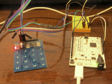
Recently I have received the TTP229 based 16 key touchpad, ordered from eBay.
Unfortunately no datasheet was provided with this module, nor could I find one from the internet.
Searching for TTP229 chip datasheet also brought unsatisfying results, since there is no datasheet available for exact chip revision used on module. However datasheets for alternative revisions were avaialble and I have found chip comparison table in some chinese blog.
With this information, I have traced, how chip is connected on the board and how it is configured. By default only 1 group of first 8 buttons works. However, if you solder pinheaders into the holes on the board, you can configure it differently with installing and removing jumpers.
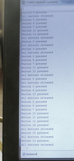
With only 2 additional jumpers installed, all 16 buttons started to work and default active low mode changed into active high. I have written a simple Arduino sketch available at my GitHub repository https://github.com/dmmedia/TTP229B_16keypad to demonstrate how the thing is working. And if you connect via SerialMonitor, you can see the button press and release events sent by the touchpad module and received by Arduino.
My next plans are to rewrite Arduino sketch into a library and start using these modules in my different experiments and projects. Modules are slim and pinheaders can be replaced by solder joints and wires where needed. Keypads can be covered with own design films or laminated paper. And the price for these modules is very low, which makes it worth to just purchase them, than making yourself.
Infinite times it was spread over the internet, that every string parameter that enters SQL query, especially user entered, should be escaped.
And again, and again, you open some critical enterprise grade project and see something like this:
CString sql = "SELECT * FROM categories WHERE category = '" + category + "'";
where category is unchecked and unescaped string that comes directly from user input.
Almost every contemporary database API contain escaping either by special method or automated while using prepared statements. But nevertheless, some our colleagues still write unsafe code. I’d suggest that it should be taught at every programming course, just by showing proper database query assembling, not a quick and dirty examples as they are now.